

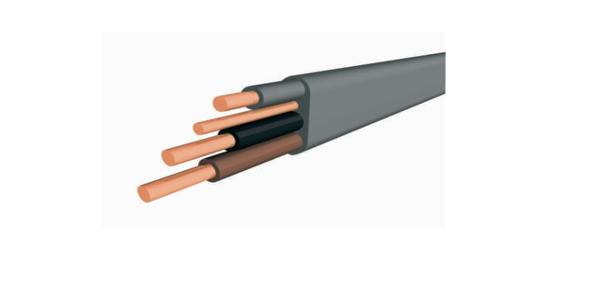
Application
Installation in walls, on boards and in channels or embedded in plaster.
Construction
Cu/PVC/PVC
1- Conductor: Copper
2-Insulation: XLPE
3- Outer sheath: LSZH
Technical Data
Min. bending radius 3 x D (D: Overall diameter)
Max. operating temperature 70ºC
Short circuit temperature: 160ºC
Details
| Construction | Cu/PVC/PVC/PVC |
|---|---|
| Standard | BS 6004 / IS 201 |
| UK Code | 6241-Y / 6242-Y / 6243-Y |
|
Cross-section (mm²) |
Reaction To Fire classification |
|
1×1+1 |
Eca |
|
1×1.5+1 |
Eca |
|
2×1+1 |
Eca |
|
2×1,5+1 |
Eca |
|
2×2,5+1,5 |
Eca |
|
2×4+1,5 |
Eca |
|
2×6+2,5 |
Eca |
|
2×10+4 |
Eca |
|
2×16+6 |
Eca |
|
3×1+1 |
Eca |
|
3×1.5+1 |
Eca |
|
3×2.5+1,5 |
Eca |
|
3×4+1,5 |
Eca |
|
3×6+2.5 |
Eca |
|
3×10+4 |
Eca |
|
3×16+6 |
Eca |

|
Nominal cross-section (mm²) |
Conductor Class |
Nominal Thickness of Insulation (mm) |
Nominal Thickness of Sheath (mm) |
Approximate overall diameter lower limit (mm) |
Approximate overall diameter Upper limit (mm) |
Max. Conductor DC resistance at 20 ºC (ohm/km) |
Max. Circuit Protective Conductor DC resistance at 20 ºC (ohm/km) |
|
1×1+1 |
1 |
0,6 |
0,8 |
3,9 x 5 |
4,8 x 6 |
18,1 |
18 |
|
1×1.5+1 |
1 |
0,7 |
0,8 |
4,4 x 5,4 |
5,3 x 6,6 |
12,1 |
18,1 |
|
2×1+1 |
1 |
0,6 |
0,9 |
3,9 x 7,2 |
4,8 x 8,7 |
18,1 |
18,1 |
|
2×1,5+1 |
1 |
0,7 |
0,9 |
4,4 x 8,1 |
5,3 x 9,7 |
12,1 |
18,10 |
|
2×2,5+1,5 |
1 |
0,8 |
1.0 |
5,1 x 9,6 |
6,2 x 11,7 |
7,41 |
12,1 |
|
2×4+1,5 |
2 |
0,8 |
1.0 |
5,7 x 10,8 |
6,9 x 13,1 |
4,61 |
12,10 |
|
2×6+2,5 |
2 |
0,8 |
1,1 |
6,4 x 12,4 |
7,8 x 15 |
3,08 |
7,41 |
|
2×10+4 |
2 |
1 |
1,2 |
7,9 x 15,6 |
9,5 x 18,9 |
1,83 |
4,61 |
|
2×16+6 |
2 |
1 |
1,3 |
8,9 x 18,1 |
10,8 x 21,9 |
1,15 |
3,08 |
|
3×1+1 |
1 |
0,6 |
0.9 |
3,9 x 9,4 |
4,8 x 11,4 |
18,1 |
18,1 |
|
3×1.5+1 |
1 |
0,7 |
0.9 |
4,4 x 10,7 |
5,3 x 12,9 |
12,1 |
18,10 |
|
3×2.5+1,5 |
1 |
0,8 |
1.0 |
5,1 x 12,6 |
6,2 x 15,3 |
7,41 |
12,1 |
|
3×4+1,5 |
1 |
0,8 |
1,1 |
5,9 x 14,8 |
7,1 x 17,9 |
4,61 |
12,10 |
|
3×6+2.5 |
1 |
0,8 |
1,1 |
6,4 x 16,8 |
7,8 x 20,2 |
3,08 |
7,41 |
|
3×10+4 |
1 |
1 |
1,2 |
7,9 x 21,3 |
9,5 x 25,7 |
1,83 |
4,61 |
|
3×16+6 |
1 |
1 |
1,3 |
8,9 x 24,6 |
10,8 x 29,7 |
1,15 |
3,08 |
|
Conductor cross- sectional area |
Reference Method A* |
Reference Method C* |
Voltage Drop |
|
Enclosed in conduit in an insulated wall |
Clipped Direct |
mV/A/m |
|
|
1 |
11,5 |
16 |
44 |
|
1,5 |
14,5 |
20 |
29 |
|
2,5 |
20 |
27 |
18 |
|
4 |
26 |
37 |
11 |
|
6 |
32 |
47 |
7,3 |
|
10 |
44 |
64 |
4,4 |
|
16 |
57 |
85 |
2,8 |
| A* For full installation method refer to Table 4A2 Installation Method 2 but for flat twin and earth cable
C* For full installation method refer to Table 4A2 Installation Method 20 but for flat twin and earth cable The above table is in accordance with BS 7671:2018 |
|||