
BS 7211
300/500 V Halogen free, flame retardant, single, twin, triple core flat cables
 |
 |
 |
| -20/+90 °C | Flame Retardant IEC 60332-1-2 | Halogen Free IEC 60754-1 |
 |
 |
 |
| Low Toxicity IEC … |
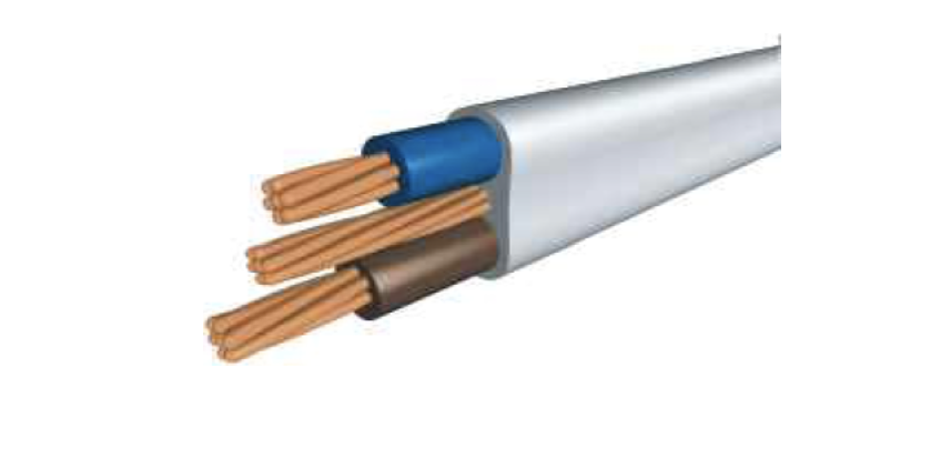
Application
Installation in walls, on boards and in channels or embedded in plaster. Low level of emission of smoke and corrosive gasses in case of fire.
Construction
Cu/XLPE/LSZH
1- Conductor: Copper
2-Insulation: XLPE
3- Outer sheath: LSZH
Technical Data
Min. bending radius 3 x D (D: Overall diameter)
Max. operating temperature 90ºC
Short circuit temperature: 250ºC
Details
| Construction | Cu/XLPE/LSZH |
|---|---|
| Standard | BS 7211 |
| UK Code | 6241-B / 6242-B / 6243-B |
|
Cross-section (mm²) |
Reaction To Fire classification |
|
1×1+1 |
Dca,s2,d2,a2 |
|
1×1.5+1 |
Dca,s2,d2,a2 |
|
2×1+1 |
Dca,s2,d2,a2 |
|
2×1+1 |
Dca,s2,d2,a2 |
|
2×1,5+1 |
Dca,s2,d2,a2 |
|
2×1,5+1 |
Dca,s2,d2,a2 |
|
2×2,5+1,5 |
Dca,s2,d2,a2 |
|
2×2,5+1,5 |
Dca,s2,d2,a2 |
|
2×4+1,5 |
Dca-s2,d2,a1 |
|
2×6+2,5 |
Dca-s2,d2,a1 |
|
2×10+4 |
Dca-s2,d2,a1 |
|
2×16+6 |
Dca-s2,d2,a1 |
|
3×1+1 |
Dca,s2,d2,a2 |
|
3×1.5+1 |
Dca,s2,d2,a2 |
|
3×2.5+1,5 |
Dca,s2,d2,a2 |
|
3×4+1,5 |
Dca-s2,d2,a1 |
|
3×6+2.5 |
Dca-s2,d2,a1 |
|
3×10+4 |
Dca-s2,d2,a1 |
|
3×16+6 |
Dca-s2,d2,a1 |

|
Nominal cross-section (mm²) |
Conductor Class |
Nominal Thickness of Insulation (mm) |
Nominal Thickness of Sheath (mm) |
Approximate overall diameter lower limit (mm) |
Approximate overall diameter Upper limit (mm) |
Max. Conductor DC resistance at 20 ºC (ohm/km) |
Max. Circuit Protective Conductor DC resistance at 20 ºC (ohm/km) |
|
1×1+1 |
1 |
0,7 |
0.9 |
4,1 x 5,2 |
5 x 6,3 |
18,1 |
18,1 |
|
1×1.5+1 |
1 |
0,7 |
0.9 |
4,4 x 5,4 |
5,3 x 6,6 |
12,1 |
18,1 |
|
|
|||||||
|
2×1+1 |
1 |
0,7 |
0.9 |
4,1 x 7,6 |
5 x 9,2 |
18,1 |
18,1 |
|
2×1+1 |
2 |
0,7 |
0.9 |
4,2 x 7,8 |
5,1 x 9,4 |
18,1 |
18,1 |
|
2×1,5+1 |
1 |
0,7 |
0.9 |
4,4 x 8,1 |
5,3 x 9,7 |
12,1 |
18,1 |
|
2×1,5+1 |
2 |
0,7 |
0.9 |
4,5 x 8,3 |
5,4 x 10 |
12,1 |
18,1 |
|
2×2,5+1,5 |
1 |
0,7 |
1.0 |
4,9 x 9,3 |
6 x 11,2 |
7,41 |
12,1 |
|
2×2,5+1,5 |
2 |
0,7 |
1.0 |
5 x 9,5 |
6,1 x 11,4 |
7,41 |
12,1 |
|
2×4+1,5 |
2 |
0,7 |
1.0 |
5,5 x 10,4 |
6,7 x 12,6 |
4,61 |
12,1 |
|
2×6+2,5 |
2 |
0,7 |
1,1 |
6,2 x 12 |
7,5 x 14,6 |
3,08 |
7,41 |
|
2×10+4 |
2 |
0,7 |
1,2 |
7,3 x 14,5 |
8,8 17,5 |
1,83 |
4,61 |
|
2×16+6 |
2 |
0,7 |
1,3 |
8,4 x 17 |
10,1 x 20,5 |
1,15 |
3,08 |
|
|
|||||||
|
3×1+1 |
1 |
0,7 |
0.9 |
4,1 x 10 |
5 x 12,1 |
18,1 |
18,10 |
|
3×1.5+1 |
1 |
0,7 |
0.9 |
4,4 x 10,7 |
5,3 x 12,9 |
12,1 |
18,10 |
|
3×2.5+1,5 |
1 |
0,7 |
1.0 |
4,9 x 12 |
6 x 14,6 |
7,41 |
12,10 |
|
3×4+1,5 |
2 |
0,7 |
1.0 |
5,5 x 14 |
6,7 x 16,9 |
4,61 |
12,10 |
|
3×6+2.5 |
2 |
0,7 |
1,1 |
6,2 x 16,2 |
7,5 x 19,5 |
3,08 |
7,41 |
|
3×10+4 |
2 |
0,7 |
1,2 |
7,3 x 19,5 |
8,8 x 23,6 |
1,83 |
4,61 |
|
3×16+6 |
2 |
0,7 |
1,3 |
8,4 x 22,8 |
10,1 x 27,6 |
1,15 |
3,08 |
|
Conductor cross- sectional area |
Reference Method A |
Reference Method C |
Voltage Drop |
|
Enclosed in conduit in an insulated wall |
Clipped Direct |
mV/A/m |
|
|
1 |
14,5 |
19 |
46 |
|
1,5 |
18,5 |
24 |
31 |
|
2,5 |
25 |
33 |
19 |
|
4 |
33 |
45 |
12 |
|
6 |
42 |
58 |
7,9 |
|
10 |
57 |
80 |
4,7 |
|
16 |
76 |
107 |
2,9 |
| The above table is in accordance with BS 7671:2018 | |||